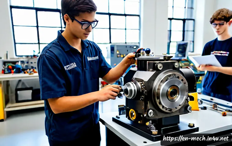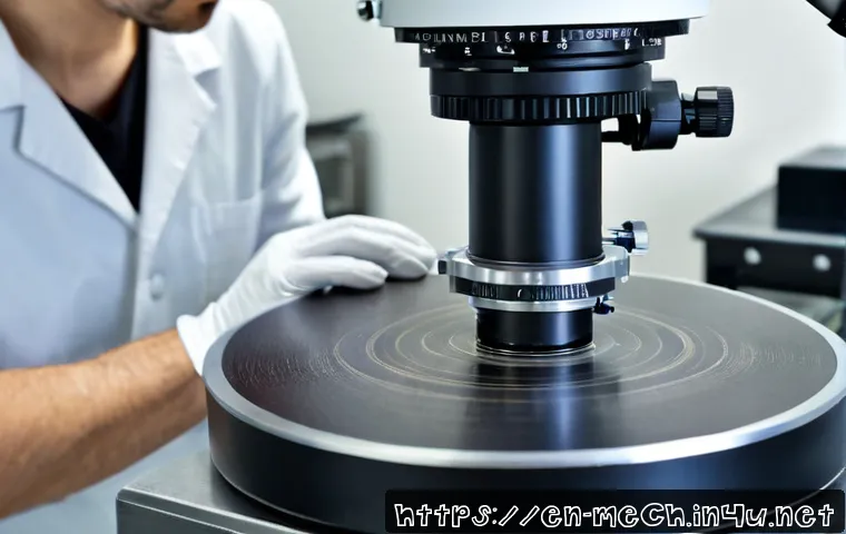
Material microstructure helps determine how a component responds to load, wear, heat, corrosion, and cracking. The right inspection method depends on the engineering question, the component’s risk, and whether routine metallography can provide enough evidence.
For many production and quality-control decisions, optical microscopy and hardness testing provide a practical starting point. Higher-resolution methods, external materials laboratories, and failure-analysis services become more useful when a defect is unclear, a component is high value, or a result could affect qualification decisions.
Microstructure is not a single property. It reflects composition, processing history, service conditions, and features such as grains, phases, inclusions, pores, precipitates, and dislocations.
A useful evaluation plan starts with the expected failure mode rather than selecting the most advanced instrument by default. Careful sample preparation and complete process records are equally important because misleading preparation marks can resemble real material defects.
At a Glance
- Microstructure affects performance: grain size, phases, pores, inclusions, and defects can influence strength, toughness, fatigue behavior, wear, and corrosion behavior.
- Routine metallography is often a sensible first step: sectioning, polishing, etching, and optical microscopy can reveal many relevant features.
- Professional testing is worth considering when risk is high: unclear failures, qualification work, weld concerns, or valuable components may require broader laboratory evidence.
| Method | Best Used For | Cost and Turnaround Consideration | Main Limitation |
|---|---|---|---|
| Optical microscopy | Routine grain structure, phases, pores, inclusions, weld areas, and general quality checks | Scope, sample condition, and laboratory workflow affect quotations and timing | May not provide the resolution or compositional detail needed for small or unclear features |
| SEM/EDS analysis | Higher-resolution surface examination and compositional information | Request sample requirements, reporting scope, and turnaround terms before approval | Results still need process history and supporting evidence for root-cause conclusions |
| Hardness testing | Checking property variation after heat treatment, welding, or manufacturing changes | Available capability and test locations can affect the scope of work | Hardness alone does not describe the full microstructure or failure mechanism |
| Outsourced metallography | Independent inspection, failure analysis support, qualification, and detailed reporting | Compare laboratory capability, sample preparation, report detail, and quotation conditions | Turnaround and findings depend on sample condition and the agreed analysis scope |
How Material Microstructure Affects Mechanical Performance
The Fast Answer: Small-Scale Structure Changes Component Behavior
A mechanical part can have the correct alloy designation and still perform differently from another part made from the same alloy. Microstructure is one reason. It reflects the internal arrangement of grains, phases, precipitates, pores, inclusions, and other features created by processing. These features can affect strength, ductility, hardness, toughness, corrosion behavior, and the way cracks start or grow.
The practical question is not simply, “Does the material look normal?” It is, “Which feature could matter for this loading and service environment?” A wear surface, a fatigue-loaded shaft, and a welded bracket may require very different inspection priorities.
Grains, Phases, Inclusions, Pores, and Defects
Grain boundaries can influence strength, ductility, corrosion behavior, and crack propagation. Phases are regions with different structures or compositions that may change after processing or heat treatment. Inclusions, pores, and preparation-sensitive features can become important when they are located near highly stressed areas or potential crack initiation sites.
Dislocations and precipitates also belong to the microstructural picture. Their relevance depends on the alloy, manufacturing route, loading condition, operating temperature, and applicable industry requirements. A micrograph should therefore be interpreted against the component’s intended function rather than used as a standalone pass-or-fail image.
Why the Same Alloy Can Perform Differently
Composition matters, but it is only one part of the engineering decision. Processing history, service environment, and microstructure work together. Casting, forming, welding, machining, additive manufacturing, and heat treatment can all change the structure seen in a prepared section. Residual stress, phase distribution, grain structure, hardness, and toughness may also change during heat treatment in many alloys.
Choosing the Right Evaluation Method for the Engineering Question
Start With the Failure or Quality Question
For routine production inspection, standard metallography may be enough to examine general structure, pore patterns, inclusions, or weld-related regions. Optical microscopy is useful for many of these inspections after careful sectioning, mounting, grinding, polishing, and etching.
When a feature is too small, surface detail is unclear, or compositional information is needed, electron microscopy may add value. SEM can provide higher-resolution surface information, while EDS can support compositional examination. Mechanical testing and hardness testing may be needed when the question concerns actual property variation rather than appearance alone.
When Routine Metallography Is Enough—and When It Is Not
Routine metallography is a practical option when the goal is to compare a production sample with an expected structure, inspect a weld region, or document visible microstructural variation. It is less complete when the investigation requires detailed surface or compositional information, or when the suspected feature cannot be resolved clearly by optical microscopy.
A useful escalation path is to begin with the simplest method that can answer the question, then add microscopy, hardness testing, chemistry review, or mechanical testing if uncertainty remains. This approach can avoid paying for analysis that does not change the engineering decision.
What to Compare Before Requesting Laboratory Work
Before selecting a metallography service or materials testing laboratory, define the required sample location, orientation, preparation method, imaging needs, and report format. Ask whether the provider can perform the required microscopy, hardness testing, sectioning, and interpretation within the desired scope. Cost, turnaround time, and equipment availability vary by region, sample condition, and analysis scope, so quotations should be compared on more than the final price.
From Manufacturing Process to Microstructural Change
Manufacturing Routes Matter
Casting, machining, welding, forming, and additive manufacturing can produce different local conditions within a component. A sample taken from one location may not represent another area exposed to different thermal or mechanical history. This is especially important near welds, surfaces, transitions, and highly loaded regions.
Heat Treatment and Property Trade-Offs
Heat treatment can alter phase distribution, grain structure, residual stress, hardness, and toughness in many alloys. That makes it a central consideration when evaluating material selection or production quality. However, the required result depends on the specific alloy, geometry, manufacturing route, operating temperature, loading conditions, and industry requirements.
Keep Process Documentation With the Sample
Micrographs become more useful when they are paired with heat-treatment records, manufacturing details, component location, service history, and relevant mechanical test results. Without this context, an observed feature may be difficult to connect to a processing step or a real service problem.
Common Inspection Errors and How to Avoid Misleading Results

Choose a Representative Sample Location
A polished section only represents the area that was removed and examined. Record the sample orientation and its location within the part. If a failure occurred, preserve the relationship between the sample and the suspected initiation area whenever possible.
Watch for Preparation Artifacts
Improper preparation can introduce scratches, deformation, pullout, or misleading features. These artifacts can be mistaken for pores, cracks, inclusions, or other material conditions. Consistent sectioning, mounting, grinding, polishing, and etching are essential before interpreting a micrograph.
Do Not Treat One Image as the Full Root Cause
A micrograph alone may not establish why a component failed. Check microscopy findings against hardness results, chemistry information, process records, mechanical testing, and service-condition evidence. This is particularly important when a finding could affect supplier qualification, production release, or corrective action.
Application-Based Priorities for Design and Quality Teams
Wear-Resistant Parts
For wear-focused applications, review hardness, carbide-related features where relevant, and surface condition. The inspection plan should reflect where contact occurs and whether the part has been heat treated or machined after treatment.
Fatigue-Critical Parts
For fatigue-loaded components, grain structure, inclusions, pores, and potential crack initiation sites can deserve close attention. The most important feature is not universal; it depends on loading, geometry, manufacturing route, and service environment. Sample location is especially important because fatigue damage may begin in a localized high-stress region.
Welded and Heat-Treated Components
Welded and heat-treated parts may have property variation between regions. Examine the heat-affected zone, adjacent material, and relevant transition areas when the engineering question involves welding or thermal processing. Hardness mapping or complementary testing may help place the microstructure in context.
Selection Criteria and Comparison Summary
Use these checks before choosing an internal inspection route or an external materials laboratory:
- Define the component function, loading condition, and suspected failure or quality risk.
- Identify the exact sample location and orientation needed for a representative result.
- Decide whether optical metallography, hardness testing, SEM/EDS, or mechanical testing is needed to answer the question.
- Compare laboratory capabilities, reporting scope, sample requirements, turnaround expectations, and quotation terms before selecting a testing provider.
- Confirm that process records and service evidence will be available for interpretation.
For internal work, inspection can be practical when equipment, trained personnel, and a repeatable preparation process are available. For unclear failures, qualification work, or high-consequence components, an external laboratory may provide broader testing capability and independent reporting. Official service pages and detailed quotation conditions are the right place to confirm sample submission requirements.
In Closing
Microstructure connects manufacturing choices to real component behavior. A clear engineering question, representative sample, and careful preparation usually matter as much as the microscope selected. Start with the evidence needed for the decision, then expand the testing scope only when the remaining uncertainty justifies it. This creates a more useful path for quality control, material qualification, and failure analysis.
Useful Information to Keep in Mind
Optical microscopy is useful for many routine inspections, while electron microscopy can provide higher-resolution surface and compositional information. Hardness testing can complement visual structure assessment after welding or heat treatment. Combining results with process records makes the final interpretation more actionable.
Important Considerations
The required microstructure cannot be defined from alloy name alone. It must be confirmed against the component geometry, manufacturing route, loading conditions, operating temperature, service environment, and applicable requirements. Laboratory cost, turnaround, equipment availability, and the meaning of a micrograph should be verified for the specific sample and analysis scope.
Frequently Asked Questions
Q1. What is the most important microstructural feature to check for a fatigue-loaded mechanical part?
A1. There is no single feature that applies to every fatigue-loaded part. Grain structure, inclusions, pores, and possible crack initiation sites can all matter. The priority depends on the component geometry, loading conditions, manufacturing route, and service environment.
Q2. When is it worth paying for SEM or EDS analysis instead of standard optical metallography?
A2. SEM or EDS may be worth considering when optical microscopy cannot resolve the relevant feature clearly, when higher-resolution surface information is needed, or when compositional information could help answer the engineering question. Compare the expected reporting scope with the decision the analysis must support.
Q3. Can heat treatment change a material’s microstructure enough to affect component reliability?
A3. Yes. Heat treatment can alter phase distribution, grain structure, residual stress, hardness, and toughness in many alloys. Whether that change improves or reduces reliability depends on the alloy, treatment process, component design, operating conditions, and required properties.